Controlling LEDs is really quite simple. As you know, they need to be current limited which is as easy as applying Ohm’s law to your given set of values. To make things even more even there’s a slew of constant current LED driver chips out there that can be had for a song. But do you have any idea how those constant current circuits work? If not, then [Giorgos Lazaridis'] guide on LED driving and controlling methods will bring you up to speed in no time.
He starts out with the most basic concept, how to light an LED using proper current limiting resistors. But from there he moves on to the juicy bits. He builds a transistor-based constant current driver, then adds voltage regulation for the circuit as seen in the schematic on the left. He moves on to the more robust and efficient method on the right which pairs a MOSFET with that transistor circuit. This is the technique found on each pin of many of those constant current drivers and functions well regardless of the voltage input level.
He’s been producing videos to go along with these articles. After the break you can watch the episode that accompanies the schematic on the left.
[Robert] put together his own illuminated coasters that know when they hold a drink. They look fantastic, thanks to professionally produced PCBs and a layered, laser-cut acrylic case. They’re much like the pagers given to restaurant-goes who are waiting for tables, but this version is much fancier (and doesn’t include the vibrating/paging feature).
The RGB-LED board is a previous project which was developed using eight surface mount RGB LED modules around a circular board. It uses an ATmega168 paired with an MBI5168 constant-current LED sink driver. The coaster enclosure gave him room for a few more items, like the pair of AA batteries which work in conjunction with a boost converter to power the device. It also houses an IR reflectance sensor which is used to detect the presence of a drink on the coaster. This is important since an on-occupied coaster looks like it would be blindingly bright if there wasn’t a glass to diffuse the intensity of the LEDs.
He mentions that incandescent light bulbs mess with the IR reflectance sensor. But there must be some way to account for ambient conditions with the code, right?
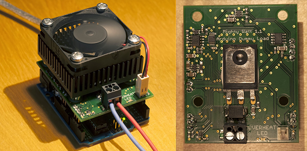
When testing power supplies or LEDs, a constant current dummy load is needed. These devices will draw a constant amount of current, regardless of the voltage at the input terminals.
[Nick] was looking for a load to test out a power supply, and found commercial offerings to be too large, too powerful, and most importantly, too expensive. This lead to the design of the Re:load, his open source alternative.
Like other constant current sources, the Re:load uses an opamp to control a pass element. While most constant current loads will just use a transistor, [Nick] opted for a BTS117 smart low side switch IC. This device has a built in current limiter, over-voltage protection, over-temperature protection, and short circuit protection, which makes it much safer. The project write up goes into detail on how the device works.
If you need a constant current load, [Nick] is selling kits on Tindie. All the design files are available on Github so that you can build your own.
Transcranial Direct Current Stimulation – or tDCS – is the technique of applying electrodes to the skull and running a small but perceptible current through them. It’s not much current – usually on the order of 1 or 2 mA, but the effect of either increasing or decreasing neural activity has led to some interesting studies. [Theo] over on Instructables wrote a tutorial for making his own tDCS suppy that will supply 2 mA to electrodes placed on the skull for everyone to experiment with.
The basic idea behind tDCS is to put the positive electrode over the part of the brain to be excited or the negative electrode over the part of the brain to be inhibited. This is a well-studied technique that can be used to improve mathematical ability. It’s not electroshock therapy (although that is a valid treatment for depression and schizophrenia) in that a seizure is induced; tDCS just applies a small current to specific areas of the brain to excite or inhibit function.
[Theo]‘s device is a simple circuit made of a transistor, resistors, and a few diodes to provide about 2 mA to a pair of electrical contacts. With this circuit and a few gel electrode pads for your head, you too can experiment with direct current stimulation of your brain.
Of course we need to warn you about putting electricity into your head. In any event, here’s a quadcopter / stun gun mashup we made. Don’t do that, either. You might get a takedown request.
By just looking at the picture above, we’re pretty sure that most Hackaday readers will have guessed by now that much power can be dissipated by this electric load. For those who don’t know, an electric load (or dummy load) is a device used to simulate a load on a system for testing purposes. This is quite handy when measuring battery capacities or testing power supplies.
The heart of the device that [Kerry] designed is based on 6 power MOSFETs, a few operational amplifiers and an Arduino compatible ATmega328p microcontroller. Sense resistors are used to measure how much current is passing through the MOSFETs (and therefore the load), the MCP4921 Digital to Analog Converter (DAC) from microchip is used to set the current command, and the load’s voltage is measured by the ATmega ADC. Measuring the latter allows a constant power load mode (as power = current * voltage). In his article, [Kerry] shows that he can simulate a load of up to 200W.
[Peter] needed to drive a high power LED for his microscope. Rather than pick up a commercial LED driver, he built a simple constant current LED driver and fan control. We’ve featured [Peter's] pumpkin candle LED work here on Hackaday in the past. Today he’s moving on to higher power LEDs. A 10 watt LED would be a good replacement light source for an old halogen/fiber optic ring light setup. [Peter] started with his old standby – an 8 pin Microchip PIC. In this case, a PIC12F1501. A PIC alone won’t handle a 10 watt LED, so he utilized a CAT4101 constant current LED driver from ON Semi. The PIC performs three tasks in this circuit. It handles user input from two buttons, generates a PWM signal to the LED driver, and generates a PWM signal for a cooling fan.
Control is simple: Press both buttons and the LED comes on full bright. Press the “up” button, and the LED can be stepped up from 10% to 100% in 10 steps. The “down” button drops the LED power back down. [Peter] even had a spare pin. He’s currently using it as an LED on/off confirmation, though we’d probably use it with a 1wire temperature sensor as a backup to thermal protection built into the CAT4101. It may be overkill, but we’d also move the buttons away from that 7805 linear regulator. Being that this circuit will be used with a microscope, it may eventually be operated by touch alone. It would be a bit surprising to try to press a button and end up with a burnt fingertip!
Not that this happens often, but what do you do when faced with a repair where you don’t know the power source but you do know you have to drive LED backlighting? When faced with this dilemma [Eric Wasatonic’s] solution was to design for ambiguity. In this interesting hack repair [Eric] needed to restore backlighting for an old car stereo LCD display. First he guaranteed he was working with a DC power source by inserting a small full-wave bridge rectifier. Then knowing he needed 4 mA to power each LED for backlighting he used some 1978 vintage current limiting diodes designed to pass 2mA each regardless of voltage source, within limits of course.
Sure this is a simple hack repair but worthy of being included in anyone’s bag of tricks. Like most hacks there is always knowledge to be gained. [Eric] shares a second video where he uses a curve tracer and some datasheets to understand how these old parts actually tick. These old 1N5305 current limiting diode regulators are simply constructed from a JFET with an internal feedback resistor to its gate which maintains a fixed current output. To demonstrate the simplicity of such a component, [Eric] constructs a current limiting circuit using a JFET and feedback potentiometer then confirms the functionality on a curve tracer. His fabricated simulation circuit worked perfectly.
There was a little money to be made with this repair which is always an added bonus, and the recipient never reported back with any problems so the fix is assumed successful. You can watch the two videos linked after the break, plus it would be interesting to hear your thoughts on what could have been done differently given the same circumstances.
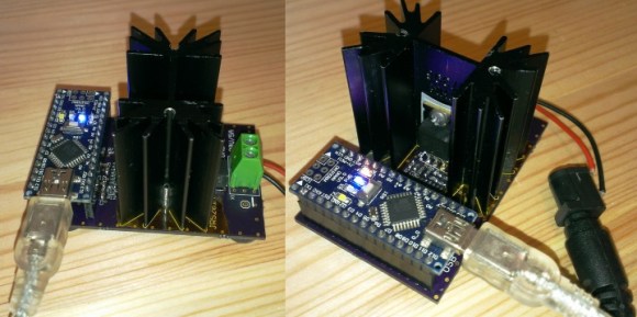
Having a big block of hot to dump current into is a very useful thing to have if you’re testing batteries, power supplies, high power LEDs, electroplating, or any thing else that would normally require a huge resistor. [Jakub] found himself in need of an electronic load, and instead of a transistor and a pot, decided to make something more automatic: a programmable load built around an Arduino shield.
The idea behind this load is pretty simple: connect a device to a FET and shunt resistor to measure current. Drive the gate of the FET with an op-amp that maintains either constant current or constant voltage. Control everything with a DAC, and you have a programmable load controlled by an Arduino.
With such a small form factor, getting rid of all that heat was bound to be a problem. For this, [Jakub] is using a 50×50 mm BGA style heat sink with a 5V fan. If it’s good enough for a big CPU, it should be able to handle dumping 70 Watts into a FET. There’s also a conservative application of thermal paste and a very small thermistor underneath the FET that’s able to be read by the Arduino. It might slowly heat up your room, but it’s not going to catch fire.
With the Arduino sketches [Jakub] wrote for his load he was able to characterize a pair of Idea batteries and figure out how much charge a three-year-old recyclable battery had. It’s a great piece of work, and if [Jakub] is willing to go through the hassle of a Kickstarter, it would make a fine crowdfunded product.
Here is a nice hack you may find very useful if you have a cheaper bench power supply that supports constant current limit protection (CC mode) and the only way to set or check your max current limit is to disconnect your circuit, short the power supply outputs and then check or set your limit. Yes, what a pain! [Ian Johnson] was enduring this pain with a couple of Circuit Specialist bench power supplies and decided to do something about it. After finding a download of the circuit diagram for his CSI3003X-5 supply he was able to reverse engineer a hack that lets you press a new button and dial-in the max current setting. Your first guess is that he simply added a momentary button to short the power supply outputs, but you would be wrong. [Ian’s] solution does not require you to remove the load, plus the load can continue running while you set your current limit. He does this by switching the current display readout from using 0–3 volts off an output shunt resistor to using the 0-3 volts output from a digital potentiometer which is normally used to set the power supplies’ constant current limit anyway. So simple it’s baffling why the designers didn’t include this feature.
Granted this is a simple modification anybody can implement, however [Ian] still wasn’t happy. A comment by [Gerry Sweeney] set him on the path to eliminate the tedious multi-button pressing by implementing a 555 momentary signal to switch the circuit from current load readout to current set readout. This 2nd mod means you just start pressing your up-down CC set buttons and it momentarily switches over the display to read your chosen max current and a few moments later the display switches back to reading actual load current. Brilliant! Just like the expensive big boy toys.
[Ian] doesn’t stop with a simple one-off hack job either. He designed up a proper PCB with cabling and connectors, making an easy to install kit that’s almost a plug-in conversion kit for Circuit Specialist bench power supplies (CSI3003X-5, CSI3005X5, CSI3003X3, CSI3005XIII). It is not a 100% plug-in kit because you do have to solder 3 wires to existing circuit points for signal and ground, but the video covering that task seemed trivial.
This hack could very well work with many other power supplies on the market being Circuit Specialist is just rebadging these units. For now, only the models listed after the break are known to work with this hack. If you find others please list in the comments.
After the break we will link to all three progressive mod videos incase you want to learn how to mod your own power supply or you could just order a prebuilt kit from [Ian].
Adding off-load constant current setting.
Replacing the front panel push-button switch with a 555 chip & relay
New pcb for the CC modification.
Single variable output 0-30VDC 0-3A Bench Power Supply #CSI3003X-5 Single variable output 0-30VDC 0-5A Bench Power Supply #CSI3005X5 Dual variable output 0-30VDC 0-3A Bench Power Supply #CSI3003X3 Dual variable output 0-30VDC 0-5A Bench Power Supply #CSI3005XIII
Some projects are both educational and useful. We believe that [Jasper's] Arduino based electronic load is one of those project.
[Jasper's] electronic load can not only act as a constant current load, but also as a constant power and constant resistive load as well. The versatile device has been designed for up to 30V, 5A, and 15W. It was based on a constant current source that is controlled by a DAC hooked up to the Arduino. By measuring both the resulting voltage and current of the load, the system can dynamically adapt to achieve constancy. While we have seen other Arduino based constant loads before, [Jasper's] is very simple and straight forward compartively. [Jasper] also includes both the schematic and Arduino code, making it very easy to reproduce.
There are tons of uses for a voltage controlled current source, and this project is a great way to get started with building one. It is an especially great project for putting together your knowledge of MOSFET theory and opamp theory!
Nerd Ralph loves cheap and dirty hacks, and for that we applaud him. His latest endeavor is a LiFePO4 battery charger that he made out of parts he had on hand for under $0.50 US. (Although we think he really made it for the fun of making it.)
The circuit is centered around a TL431 programmable shunt regulator, which is an awesome and underrated chip in its own right. If you don’t know the TL431 (aka LM431), you owe it to yourself to fetch the datasheet and pick up a couple with your next electronics part order. In fact, it’s such a great chip, we can’t resist telling you about it for a minute.
TL431
Despite its misleading electrical symbol, think of the TL431 as being a voltage-activated switching transistor. When the voltage on the reference pin is lower than 2.5V, the transistor doesn’t conduct. When the voltage on the reference pin is higher than 2.5V, the transistor acts as a closed switch, sinking around 100 mA of current to ground.
If you tie the reference pin to the cathode, the TL431 does behave like a zener diode that has a breakdown voltage of 2.5 V, but that’s selling it short. The TL431 is a full-fledged IC with a precision voltage level reference, a comparator, and the active transistor all bundled up inside. The ability to put different voltages on the reference pin and the cathode make it interesting.
In the simplest circuit, you could drive an LED with a TL431. Connect an LED and a current-limiting resistor up to the cathode and ground the anode of the TL431. Then, when the voltage on the reference is higher than 2.5V, the LED will light up brightly. 2.5V isn’t interesting to you? You can add a voltage divider to increase the threshold to any value above 2.5 V that you’d like. Shown here is an LED that only lights up when the input is 5V or greater. You can use this idea anywhere you need a voltage activated switch, for instance as a battery’s low-voltage monitor.
Battery Chargers and Feedback
The TL431 is fine as a switch, but it thrives on feedback. To make a voltage regulator from the LED circuit shown here, all you need to do is add a transistor in place of the LED; have the TL431 turn the transistor on when the voltage drops below a target voltage and off when the voltage rises above. Indeed, this cheap and cheerful voltage regulator application is where almost all of the TL431s end up — providing voltage regulation in switching power supplies. You’ve probably got a few in your computer’s power supply right now, as a matter of fact.
So let’s go back to Nerd Ralph and his battery charger. Ralph’s simple battery charger is essentially this simple voltage regulator circuit. He chose the voltage-setting resistors R1 and R2 to give him 2.5 V on the TL431 when the output sees 3.6 V, the voltage which a LiFePO4 battery is basically done charging.
To see the TL431 in action here, first imagine that it’s not conducting (off). Current flows from the power supply through RB1 and into the transistor, turning it on. The voltage at Vout increases, the battery charges, and the voltage in the middle of the voltage divider increases proportionately. When it reaches the 2.5 V threshold, the TL431 turns on and draws current, robbing the transistor of its base current and lighting the LED at the same time.
Because LiFePO4 batteries like to be charged with constant current nearly up to the end of their range, Ralph picked the transistor’s base resistor RB1 to limit the maximum current delivered to the batteries. He tested the output current into a half-charged battery to verify that he was in the right ballpark.
Now we’re not entirely sold on this being a constant current charger circuit. The basic circuit is a voltage regulator, after all. Relying on the transistor’s current gain to be constant over temperature or across different transistors is a bit sketchy — for instance the Art of Electronics warns you explicitly about the variability of the current gain value. But the LiFePO4 cells look like they’re pretty robust compared to their other lithium battery cousins, and the voltage profile only really varies from 3.4 V at 10% charge to 3.6V at 90% charge. Constant enough.
It’s also missing a bunch of things we like to have in other LiPO chargers, like battery temperature sensing and disconnect at charge completion. But again, the LiFePO4 cells are robust enough to overcharge that he’ll probably get away with it if he doesn’t leave the batteries in the charger for very long. It’s a hack, after all.
Kudos and Comments
TL431 in its natural habitat: next to an optoisolator in a cheap switching power supply
So first, we’d like to thank Ralph for reminding us of a very useful part for minimalist electronics. The TL431’s datasheet is full of cool applications, and the combined functions of a voltage reference and comparator-driven transistor in a couple-cent piece of silicon make that work. If you need a voltage-triggered switch anywhere in your project, you now know where to look.
What do you think of Ralph’s charger design? Do you have any favorite tricks for the TL431? What piece of silicon would you rate as an unknown gem in the rough? Let us know in the comments and send in a tip for parts you’d like to see featured in the future.
Is it ironic when a YouTube channel named “The Current Source” needs to build a current source? Or is that not ironic and actually just coincidental?
Regardless of linguistic considerations, [Derek], proprietor of the aforementioned channel has made and disassembled a few current sources in his day. Most of those jobs were for one-off precision measurements or even to drive a string of LEDs in what he describes as a pair of migraine-inducing glasses. Thankfully, The junk box current source presented in the video below is more in service of the former than the latter, as his goal is to measure very small resistances in semiconductors using Kelvin clips.
The current source uses a 24-volt switch-mode power supply and the popular LM317 adjustable voltage regulator. The ‘317 can be configured in a constant current mode by connecting the chip’s adjustment pin to the output through a series resistance. A multiturn pot provides current adjustment, although the logarithmic taper is not exactly optimal for the application. We spotted a pair of what appear to be optoisolators in the build too, but there’s no schematic and no discussion of what they do. [Derek] puts the final product to use for a Kelvin measurement of a 0.47-Ω 1% resistor at the end of the video.
We’re glad to see [Derek] in action; you may recall his earlier video about measuring his own radiation with a Geiger counter after treatment for thyroid cancer. Here’s hoping that’s behind him now.
‘Tis the season for dropping hints on what new doodads would make a hacker happy, and we have to admit to doing a little virtual window shopping ourselves. And as a decent bench power supply is on our list, it was no surprise to see videos reviews that the hive mind thinks will help us make a choice pop up in our feed. It’s a magical time to be alive.
What did surprise us was this video on a mashup of two power supplies, both of which we’ve been eyeing, with the result being one nicely hacked programmable bench PSU. It comes to us courtesy of [jeffescortlx], who suffered with one of those no-name, low-end 30V-5A bench supplies that has significant lag when changing the settings, to the point that it’s difficult to use, not to mention dangerous for sensitive components.
So he got a hold of a Riden RD6006 programmable buck converter, which is something like those ubiquitous DPS power supply modules we’ve seen so much of, only on steroids. The Riden takes up to 70V input and turns it into a 0-60V output at up to 6 amps, at constant current or constant voltage. It also just happens to (almost) fit as a replacement for the faceplate of the dodgy old supply. A few SMD resistors simulate the original front panel pots being pegged so that the supply outputs maximum voltage and current, and a little finagling with the case and fan was needed to fit everything up, but the finished product actually looks really good, and fixes all the problems of the original.
We love this hack, and may well cobble this together for our bench.
There’s a problem with fuses. On the face of it, testing would seem to be a one-shot deal — exceed the rated current and see if it blows. But once you know the answer, the device is useless. If only there were a way to test fuses without damaging them.
As it turns out there is, and [Kerry Wong] weaves quite a tale about his attempts to non-destructively test fuses. The fuses in question are nothing fancy — just the standard glass tube type, from a cheap assortment kit off Amazon. Therein lies the problem: can such cheap devices be trusted? Finding out requires diving much deeper into the technology of fuses than many people will have done, including understanding how the thermal and electrical characteristics of the fuse element behave.
[Kerry]’s test setup is simple, consisting of a constant current power supply and a voltmeter across the fuse to measure the voltage drop caused by the resistance of the fuse element. As he ramps up the current, the voltage drop increases linearly due to the increase in resistance of the alloy with increasing temperature. That only lasts up to a point, where the fuse resistance starts increasing exponentially. Pushing much past the point where the resistance has doubled would blow the fuse, so that’s the endpoint of his tests. Perhaps unsurprisingly, his no-name fuses all went significantly beyond their rated current, proving that you get what you pay for. See the video below for the tests and an analysis of the results.
It’s handy to know there’s a way to check fuses without popping them, and we’ll file this one away for future reference. Don’t forget that you should always check the fuse when troubleshooting, because you never know what the last person did to it.
Normally, when a project calls for addressable LEDs, we just throw a strip of WS2812s and an Arduino together, cobble together some code from the examples in the FastLED library, and call it a day. We don’t put much thought into what’s going on under the hood, unless and until we run into an LED project that’s a little more challenging.
Inventor [Leo Fernekes] found himself in such a situation recently, when he pitched in on an LED art installation. The project called for rings of LED bars around the trunks of trees on a private estate. The physical size of the project and the aesthetic requirements created significant challenges, though. One of these was finding a way to control the LED bars, each of which draws about 100 mA and needs to be very smoothly dimmed. [Leo] looked at the WS2811 LED driver, but found that the low drive current and the 8-bit PWM output failed to tick either of those boxes.
[Leo] solved both problems by using two of the three PWM channels on the chip in concert — one to control the current and one to PWM the LED. The circuit he came up with is deceptively simple — just four transistors, a Schottky diode, and a bunch of passives. The other clever bit is the data interface between LED bars, which can be configured as either single-ended or differential. This allows the same interface to be used for the short distance between bars on a tree, and the longer runs between trees.
As usual, [Leo] does a great job of explaining his design and how it works, which we find very instructional. He did something similar when he managed to dim a non-dimmable LED fixture.